


PBOT 2018 Entry Level Mobile Robot Controller – Introduction

PBOT 2018 Entry Level Mobile Robot Controller – Introduction
Features:
- Operates on single Lithium Ion (included) battery
- Efficient Motor Driver Circuitry enables the operation of motor to its maximum power at the same time eliminating the need for an heat sink.
- On board 4 Channel Servo Motor Driver port
- On board Li-on battery Charger. You can charge the battery even using you old cellphone charger.
- Sensors managed by independent controller.
- Collision sensor are pulsed to saved battery power.
- Line sensors are digitally calibrated, making calibration process delightfully easy
- Arduino Compatible
- Program it using Arduino IDE 100% code compatible with Arduino UNO(1)
- ATMEGA168 microcontroller sporting 16K User program memory space.
- Arduino external I/O pin layout allows you to plug in any Arduino compatible shield(2).
Notes:
1: PBOT 2018, with its ATMEGA168 microcontroller, offers memory space (FLASH/RAM/EEPROM) half of what Arduino Uno offers. But this hardly matters. 16K memory space is more than enough to fit even fairly advanced Mobile Robot application.
2: Analog pins A4 and A5 are used to interface with the system controller, hence are not available for user shields/application.
General Specifications:
- Battery: 3.7v Li-on Rechargeable Battery
- Optional: 7.2V NI-MH 800mAh rechargeable
- With boost dc voltage output: 7.2vdc
- On Board Peripherals: – IC ATmega168 w/ 16KB Flash Memory – IC A3966 Dual Full-bridge PWM Motor driver – 2-Ch DC Motor 6V 1.5A – 3-Ch IR Line Sensor -CNY70 sensor, 10mm range – With Battery charger circuit for 3.7v
- PCB Dimension: 62X67mm
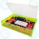
Major Parts Presentation PBOT 2018
 * SW5 – Booth select – when uploading a code; Run select – received pin connected to run the program and for gathering the data through wireless module devices (Bluetooth, WiFi, RF modules or any serial connections).
3 Channel Collision Sensors
The 3 Channel collision sensor detects objects reflected the beam send by an array infrared emitter. The beam will reflect back in a sec and gives the mcu an output. If the objects comes close on the sensors detection view, the beam refelects back to trigger the detector.

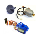
PBOT2018 controller has four servo channels on board with built-in 3 pins male connector to easy connect the servo motors. P3 to P6 is the pin name of servo.Note if you are using SG-90 and other servo motors when you connect it directly to the PBOT2018, you should have them powered by a seperate supply from the PBOT2017 controller board rather than from the boost converted voltage from 3.7v battery, because servo motors can use a bit of current, to cause a voltage distortion or power off/ shutdown the whole system.
 But using 7v2 Ni-MH battery it can supply all the PBOT2018 controller with servo motors like ZS-F135MG (e-GRA) and SG -90. We recommend to use serparate supply for the servo if you are using high torque type offrom MG-995 and higher.
Proper use of Servo Supply Source
- If you are using 3.7V battery, you need another 6V supply to power the servos (A).
- For 7.2V Ni-MH, just put a jumper to power it (B).
A

B

3 Channel Line sensor
The sensitivity of the three comparators can be separately set by adjusting their reference voltage through their corresponding adjust trimmers.
The process is trouble-free and straightforward. The reference voltage is fed to the positive (+) input of the comparator. Then if the analog input fed through the – input exceeds the reference voltage, the comparator output switches to logic low. Or else, it assumes a logic HIGH state.


An analog comparator mostly converts analog voltage appear at its input into a single bit digital
logic signal.
3-Channel analog comparator is a common analog interface circuit. It can be used as well with other sensors with 0-5VDC output range functioning as a single bit analog to digital converter (ADC).
Line sensor Calibration Instructions
- 1. After uploading your code for line sensors. Turn OFF the POWER switch.
- 2. Place the eGizmo PBOT 2018 controller to the Black line then Press and Hold LINE CAL and SYS RST, while pressing and holding the buttons, Turn ON the POWER Switch. LN2 (D12 LED indicator) is ON.
- 3. First RELEASE the SYS RST followed by LINE CAL. Make sure the 3CH Line sensors are faces on the Black line and you will see the LN1 and LN3 (D11 and D13 LED indicators) are Turn ON and LN1 is blinking. Now Press LINE CAL once for the Black color calibration.
- 4. Next, if the L3 (D13 LED indicator) is blinking. Place the 3CH Line sensors on the White track. then Press LINE CAL again once for the White color calibration. After that you will see all the LEDS for linesensors are ON.
- 5. Now your eGizmo PBOT 2018 Controller line sensors are calibrated. Then Press the RESET button. You can now trace the line and DONE.
Motor Driver
The Motor driver circuit is the connection circuit between your controller and the motor. The controller can scheme the operation of the motor through a series of simple logic output combinations through this circuit.
A4986 dual full-bridge PWM Motor driver with overcurrent protection and internal synchronous rectification control circuitry is provided to improve power dissipation during PWM operation.

The outputs are protected from shorted load and short to ground events,to protect the driver from thermal damage.
Motor Connections:


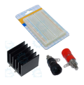
Charging and Power Circuit
This is the charging section for 3.7v Li-on Battery 1580mAh (BT2) and 7v2 Ni-MH battery (BT1) connections (Optional). SW1 Power Switch ON, OFF/Charge.

| Note: If the power shutdown accoured, kindly unplug the battery BT2 then plug In again. (The battery has its own circuit protection.) Also apply this if you trying to upload your codes or charge the battery. |
The PBOT2018 controller board has a TP4056 module for Li-on battery charger (J3), just connect USB cable Type Mini B to Type A to the module with battery plug on the BT2 connection. This module has indicator the Red LED lights will on, if it is the battery is on charging mode. If the battery is fully-charged the Green LED indicator will lights on.
The board also has a DC-DC booster converter from 3.7VDC to 7.2V and the maximum current limit for the M-BOT is 1.5A,
Important: Charge your battery,if not enough power to run the motors. Full Charging hours approximately 1 hour and 32 mins (2 hrs max).

The TP4056 is a complete constant-current/constant-voltage linear charger for single cell lithium-ion batteries. Its SOP package and low external component count make the TP4056 ideally suited for portable applications. Furthermore, the TP4056 can work within USB and wall adapter.
gizDuino w/ ATMEGA168 IC on board
Most important on board is the microcontroller, the PBOT2018 controller has a built-in ATmega168P IC with compatible shield and the software is Arduino IDE. It has its own library to use the “eGizmo_PBOT2018 library” must be added to your My documents> Arduino>libraries. Some examples are Line follower, Collision avoidance, solving maze, Motor Test, and servo controlled.

Prolific Driver:
With Built-in PL2303 Driver U10 to connect easily on your computer via USB mini type B P8, just install the driver manually. You may visit the site and downloads at link.

This device will let your microcontroller communicates with the PC through a USB port the same way you will with a PC COM port.
USB Cable Type A- mini B.