Guidelines for Using gizDuino LIN 5V Power Output

The Arduino and gizDuino boards have on-board 5V regulators whose output is also made available for the shield adds on. gizDuino even has a special 4-pin 5V port that can be used to power off board components and circuits.

The presence of this 5V supply lines does not means, however, that it can power up any number of 5V shields or devices. The truth is, the on board 5V regulator does not posses the ability to power anything else much other than itself. Ignoring this limitation can results in lot of head scratching project failures and erratic behavior (with the board and user). The on-board 5V power supply is not a connect-all-you-can source. It pays to understand its limitations so you can spare yourself from potential troubles from misuse.
Just exactly how much +5V power can you draw?
The gizDuino LIN can be powered from two sources: PC USB, or through an external power supply. The power that can be drawn differs appreciably depending upon which one is actively sourcing the +5V rail power. The gizDuino LIN automatically switches to external DC source when it detects its presence (Vin>7V).
Powered by USB
Your PC’s USB 2.0 port is capable of delivering currents up to 0.5A. USB 3.0 ports can do up to 0.9A. The gizDuino has a self resetting fuse that will trip when current in excess of 0.75A pass through it long enough. With this in mind, your devices should not draw more than 0.75-0.11= 0.65A when plugged in a USB 3.0 port, or 0.4A in a USB 2.0 port. If you have no idea what’s your PC’s USB version, assume 0.4A as safe the working limit.
Powered by External DC supply
Here things gets a little more interesting. The on-board 5V regulator of the gizDuino now comes into play, and its safe working limits is determined by how much voltage your external DC supply is putting in.
The on-board IC regulator is rated at 0.5A. If the external power supply can supply that much current, then we can safely draw 0.5A, right?
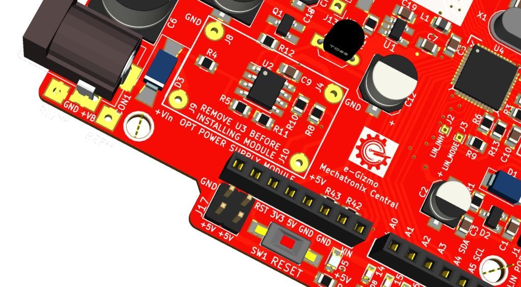
Well, not quite. The limiting factor is actually the heat generated by the on-board regulator. As you can easily noticed, the on board regulator are not fitted with a heatsink. Both the gizDuino LIN and Arduino Uno rely on the PCB copper pattern to dissipate the heat, which is not enough under certain conditions that we will discuss next.
gizDuino LIN uses a 78M05 type linear voltage regulator in T0-252 package. The thermal characteristics of this device is shown in Fig. 13 below2.

The 103C/W curve is the thermal limit of the 78M05 without the benefit of any heatsink. This represents our worst case scenario- we will set our limiting parameters based on the estimates we get here. In reality, as we already mentioned, the PCB was designed to function like a heatsink. Our gizDuino LIN will actually perform better, that give us the margin to ensure we stay within the safe zone.
Let’s do some calculations
Important Note: The actual current drawn from the +5V rail is actually the sum of current drawn from +5V and +3.3 rail. In the following discussion, we will assume +3.3 rail is not loaded (0.0 A) for clarity.
The linear voltage regulator used in gizDuino and Arduino requires an external input voltage that is higher than the 5V output to make the regulator do its work. gizDuino LIN requires 7.0V as minimum input voltage.
The power the on-board regulator has to dissipate can be calculated from the following formula:
I= P/(Vin-5.4)
where : P- power in watts
I – Input current in amp
Vin – Input Voltage 5.4 = 5.0V output voltage + 0.4V Reverse protection diode drop3.
Remember, the gizDuino circuitry draws power from the same regulator, hence you should always subtract 0.1A from the results to arrive at a maximum safe current that can be drawn.
Going back to Fig. 13, The 103C/W line tells us that at 25C ambient temperature, the device can safely dissipate roughly 1.0W of power.
Hence, at 7V external DC input, the safe current that can be drawn can be calculated as
I = 1.0/(7-5.4) = 0.625A
But since the regulator current max out at 0.5A, the safe limit is then 0.5A- 0.1A or 0.4A. This, by the way, should be also taken as the design peak current capability of the gizDuino LIN 5V output.
Now, let’s find out what the safe current will be with a 9V external DC source:
I= 1.0/(9-5.4) = 0.278A
That gives us 0.278-0.1 = 0.178A.
At 12V external DC source:
I= 1.0/(12-5.4)= 0.1515A
The maximum current that can be drawn out with a 12V source is then 0.1515-0.1, or just 0.0515A! What this tells us is, you can hardly use the 5V power output of the gizDuino (or Arduino Uno4) to power anything else when you operate it with an external 12VDC source!
This reduction in ability to source current due to temperature rise is also known as Thermal Derating and is inherent in all linear power supply circuits.
Choosing an External DC Source
The current we just discussed actually describes the sustained average current that can be safely drawn. It is alright to connect a device that peaks for a short period at 0.4A, even with a 12V external DC source, as long as the average remains within the computed limit.
And because of the heatsinking benefit provided with the PCB design, the actual limit is actually significantly higher than what the calculations will tell you. For example, our calculations at 9V input showed 0.178A as our safe limit. We actually tested the gizDuino LIN with a 0.3A load (9V input) and let it run for 4 hours. The gizDuino LIN run hot, but did not sustained any damage.
To sum it up:
- Use an external supply with a low source voltage and with an amp rating of at least 1A. gizDuino works best with an external supply voltage of 7.5 to 9VDC.
- Use a separate power supply for add-on circuits (shields) and devices that requires appreciable amount of power. If the shield has a power supply input terminal (e.g. DC jack), that is a strong indication that a separate supply must be used. Examples of these circuits and devices are relay boards, motors, and gsm modules.
If your gizDuino/Arduino frequently crashes (or behaves erratically) and has add-on devices that draws power from the on board +5V rail, simply using a separate supply for the add-on may eliminate this problem.
DC/DC Converter Option
But then, there are instances where hefty power must really be drawn out from the on board +5V, and a separate supply is not practical or simply not desired. Like with battery operated projects. Or maybe, you are building a gizDuino project that has to be powered from an existing DC power distribution that has a voltage too high for the on board regulator to take.
That’s why the gizDuino LIN has this so called DC/DC Converter option. You can install it yourself or buy with the option already installed. The DC/DC converter board are actually Switch Mode Power Supply SMPS devices – non linear but very efficient power supply. And since they are efficient, they hardly heat up during operation. That means, there is practically no Thermal Derating to be worried about. If your SMPS can supply, say 2Amps, it can do 2Amps throughout its input operating supply range!
MP2303-5 Option – This DC/DC converter module will allow your gizDuino LIN to operate safely with external DC supply input of up to 28VDC. And if your external DC source can supply at least 20W to your gizDuino LIN circuit, you can have a hefty 2.9A at the +5V rail available for your add-on. You
B6286-5 Option – You will probably need this if you are building a portable battery operated gizDuino LIN project. This DC/DC converter allows your gizDuino LIN to operate and generate a +5V rail from a low voltage external supply, such as from a 3.7V Lithium Ion battery. And if you are using a battery with enough ampacity, you can draw as much as 1A from the +5V rail. The B6286-5 will operate with an input supply voltage range of 2.3V to 5.5V. Warning – with B6286-5 option installed, you will destroy your gizDuino LIN if voltage in excess of 6V is applied at the external supply input.
Note 1. The gizDuino LIN can draw as much as 0.1A for its use, hence, 0.1A should be substracted from the total available current.
Note 2. source: LM78M05 Datasheet published by Texas Instruments
Note 3. The gizDuino LIN uses a schottky diode in series with the DC jack input to prevents the gizDuino LIN from being fried if a wrong polarity external power is plugged in the DC jack. This diode contributes an approximately 0.4V drop in the input voltage.
Note 4. A YouTube video uploaded by Rouge-Electron shows an Arduino Uno going up in flames seconds after a 14.8V external DC input and 0.65A load current is drawn.


