


gizDuino Latch and Switch Button
02 Apr

Posted By
0 Comment(s)
2446 View(s)
Demo:
Review:
What is Button?

A button that is pushed to operate an electrical device.
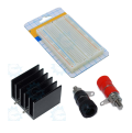
Materials Need:
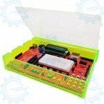
1 x gizDuino PLUS ATmega644P Starter kit
1 x Clear LED 5mm
1 x Green LED 5mm
2 x 560 Ohms Resistor/p>
2 x 10k Ohms Resistor
2 x Tact Switch Button 4pins or 2pins
1 x USB Cable
8 x 1pin Jumper Wire (male-male)
Schematic Diagram:

Wiring Connection:
LED:
Digital pin 11/10 --> (+) Anode LED
(-) Cathode --> 560 ohms --> Ground
Button:
Digital pin 3/2 --> Button pin 1--> 560 ohms --> Ground
Button pin 2 --> Ground

 by
by