


LabVIEW + gizDuino UNO-SE: Controlling a DC Motor with potentiometer using Hulkster Motor Driver

Demo Video
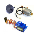
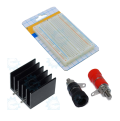
List of Primary Components needed:
1. 24V DC geared Motor
1. Potentiometer 10K
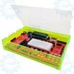
Hardware Configuration
To assemble the components follow the steps:
1. First, connect HulkSter Motor Driver's power inputs (+), (-) to gizDuino UNO-SE's (+5V), (GND) respectively.
2. Then, connect Potentiometer to the gizDuino UNO-SE, (-)pin to GND, (+)pin to (+5V), and Output pin to AnalogPin 0 (A0).
3. Then, connect HulkSter Motor Driver's INA, INB, PWM to D4, D5 and, D6 respectively.
4. Finally connect your DC Motor to its corresponding ports on the HulkSter Motor Driver.

Writing the LabVIEW program
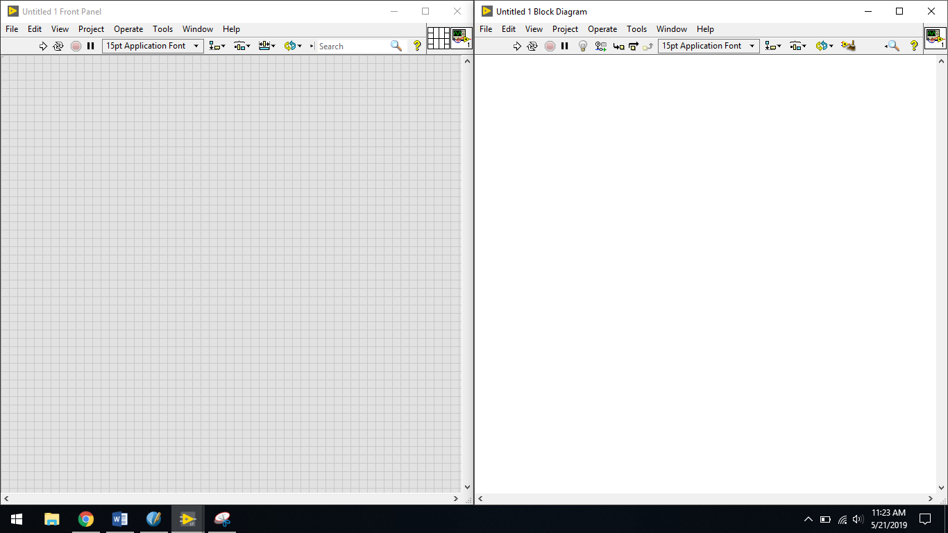
We will now write a new LabVIEW program from scratch so that you can see how the LINX interface for gizDuino UNO-SE is working. To start the process, open LabVIEW and create a new blank VI.
VI File: SampleDCGearedMotorContorl.vi


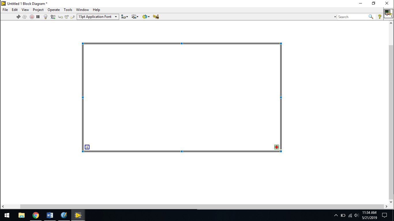
These two windows will appear (Front panel on the left, and the Block Diagram on the right)
Note: The said windows was purposely placed to form "Split Screen" mode.
First, right click on the Block Diagram then Structures then click While Loop and then perform a "Drag" depending on how big your loop will be.

Then right click again and go to "MakerHub" > LINX and you will see the different "VI's" that LINX provides for you to be able to use LabVIEW interface to control your gizDuino UNO-SE.
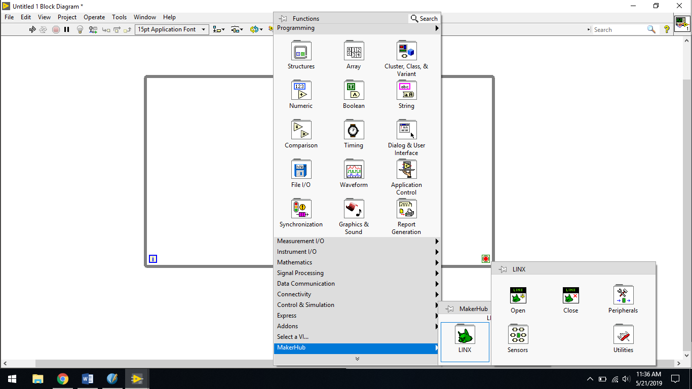
After that, we will place our first elements from the LINX package. The first elements we need to place are the LINX initialize and stop elements, which are necessary to tell the software where to start and where to stop. You can find both boxes in the functions panel by going to the MakerHub submenu.
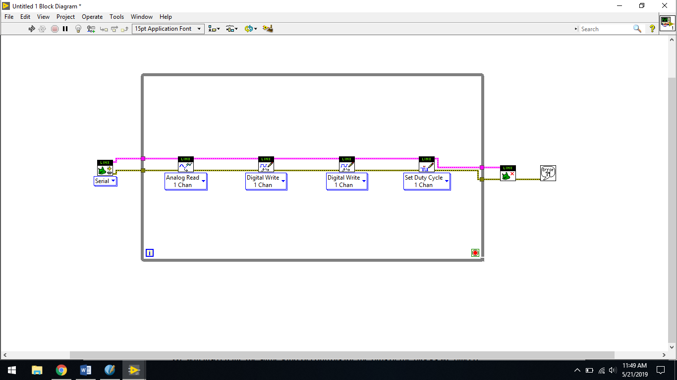
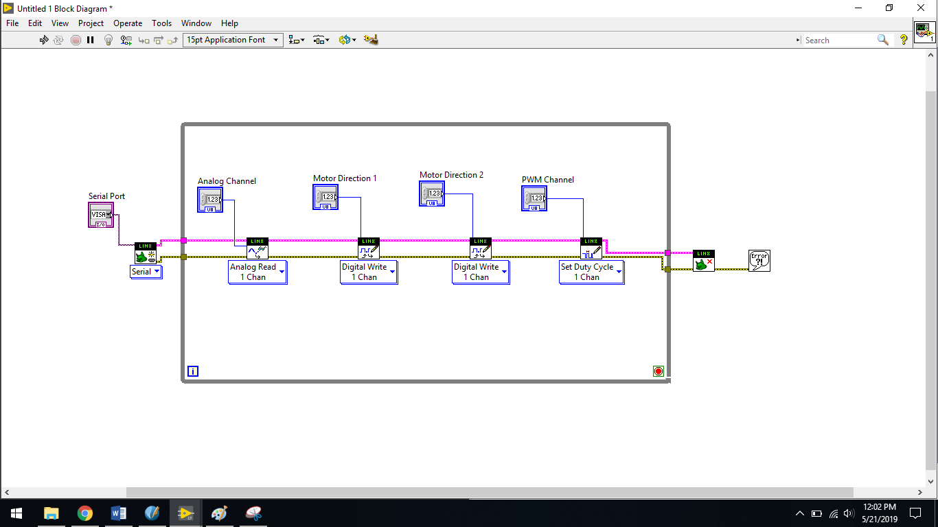
From the same submenu, place two Digital Write blocks (which will be used to control the motor direction) and one Analog Read Block (which will be used to control the motor speed) and one PWM Block to read the value of the Analog Block. Note that you can find these blocks under the Peripherals menu. I also added a simple error handler at the end of the VI, just after the stop block. This handler can be found under the Dialog & User Interface menu. This is the result:

Then, connect the error-out pin of this block to the error-in pin of the first digital
block and so on till the end block. After that, do the same with the LINX resource pins
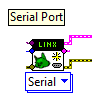
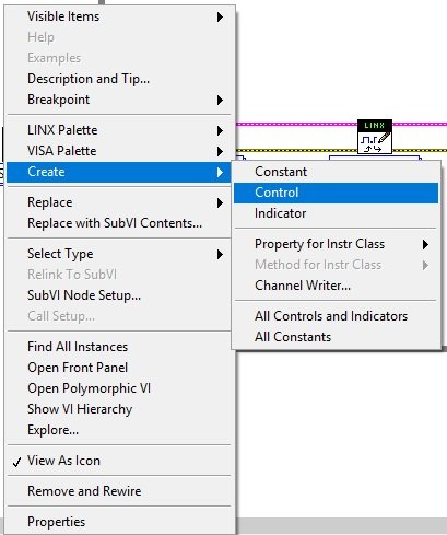
Now, we will feed the blocks with some inputs. First, add a serial port to the initialize block by going to the serial port pin of
the block and right-clicking on it.
Then, go to Create | Control to automatically add a serial port input. You will
note that the corresponding control is automatically added to Front Panel as well.
Rename this control to Serial Port so that we can identify it in Front Panel.
We will also create the same kind of controls for the pins of the blocks we placed
earlier. For each block, simply add inputs by right-clicking on the pin's input and
then going to Create | Control. Also, rename all of these controls so that we know
what they mean later in Front Panel.
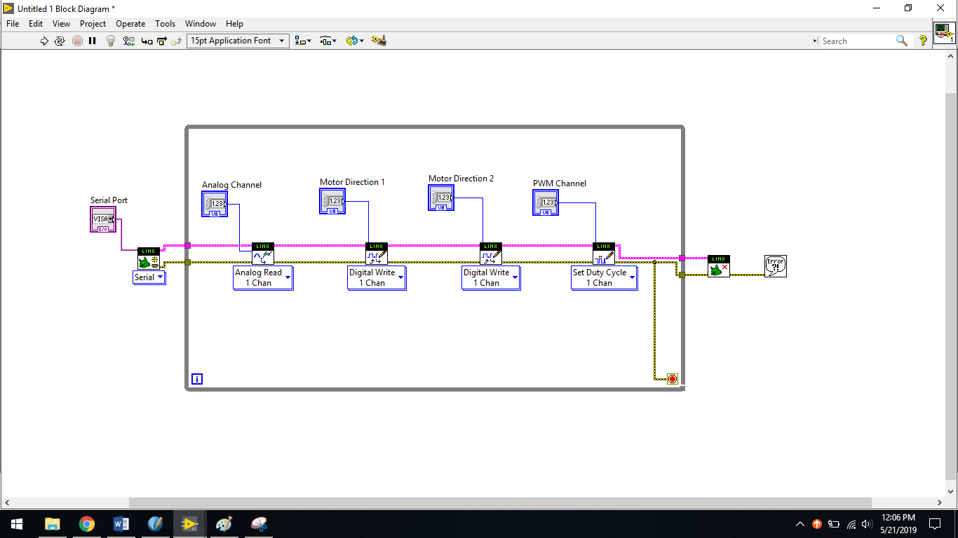
This is what it looks like on the Block Diagram (left) and Front Panel (Right)


Block Diagram
Front Panel

We also need to add an end condition for the While Loop. To do so, we need to connect the little red circle that is located in the bottom-right corner of the While Loop. In this chapter, we will simply connect the error wire directly to this red circle.
To do so, just select the input pin of the red circle and connect it to the bottom error
wire inside the VI.
We will now feed the values of the different blocks that we will change from Front
Panel to control the motor. At this stage, we will keep it simple: we will have some
on/off control for the direction and a simple text box for the speed of the motor.
First, let's set the direction that we need to feed on the two first LINX blocks in our
VI. The Hulkster Motor Driver requires to be fed with opposite signals on the two direction pins
for the motor to rotate in a given direction. For example, when the first Digital Write
block is on, we want the second one to be off and vice versa.
To do so, we will first create a control block on the first Digital Write block, again by
right-clicking on the input pin and then going to Create | Control. Then, we will go
to the Functions menu, in Booleans, choose a Not element, and use it to connect our
control to the second Digital Write channel. This way, we are sure that these two
will always be in opposite states.


Finally, connect the Voltage pin of the Analog Block of the Duty Cycle Pin of the PWM Block

You can now go back to Front Panel and have a look at all the elements that were
automatically added for you. Organize them a little bit so that it is easier to control
the motor.
It's now time to test the VI. First, set all the correct pins and your Serial Port,
as shown in the preceding image. Then, click on the little arrow in the toolbar
to start the VI.
Connect your gizDuino UNO-SE to your PC, then wait for approximately 5-8 seconds because your board is establising the connection to LabVIEW. Then click the small white arrow on the toolbar.
Congratulations! you have accomplished your first ever LabVIEW to gizDuino UNO-SE sample Project.
Documented by: King Johnnel Olgado