Menu
Menu
Your Cart

e-Gizmo Raindrop Detector Module
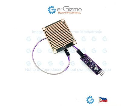
e-Gizmo Raindrop Detector Module
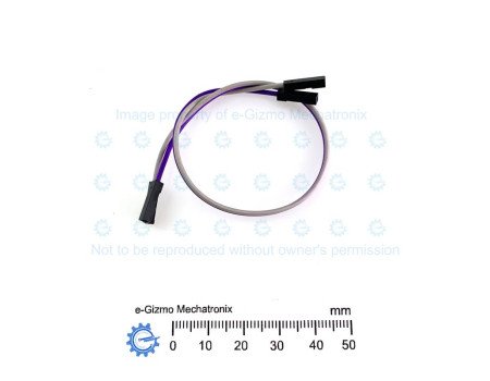
New
e-Gizmo Raindrop Detector Module
₱59.00
  • Stock: In Stock
  • Brand: e-Gizmo
  • Product Code: 211100073

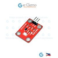
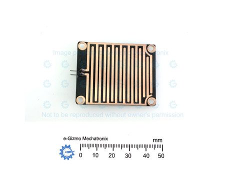
e-Gizmo Raindrop Sensor Module is an easy-to-use, dual-output sensing board designed for weather monitoring, automated window/roof closures, wiper controls, and smart agricultural systems. It features a dedicated sensing PCB with interleaved copper traces and an interface module that processes both real-time analog levels and adjustable digital threshold triggers. Compatible with 3.3V and 5V microcontrollers (such as Arduino and Raspberry Pi), it offers flexible integration for hobbyist and industrial automation projects alike.

Key Features & Hardware
* Dual Output Modes:
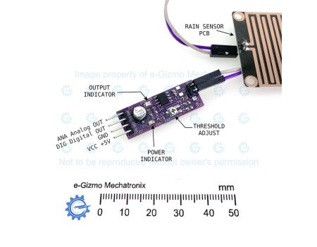
* Analog Output (ANA): Delivers a continuous voltage level proportional to the amount of water present on the sensor board.
* Digital Output (DIG): Provides a clean, logic-level switching signal (normally HIGH, switching LOW upon rain detection).
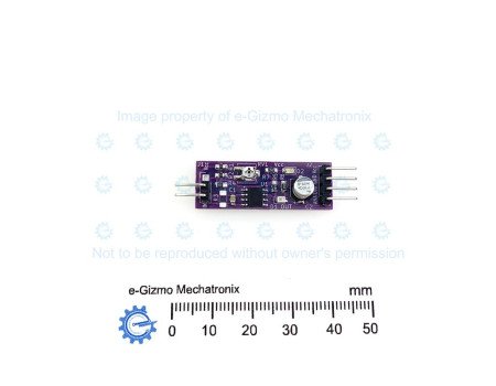
* Onboard Potentiometer (THRESHOLD ADJUST): Allows precise sensitivity calibration for digital switching thresholds (trigging on light mist vs. heavy rain).
* LED Status Indicators:
* Power Indicator (D2): Lights up when the board is powered.
* Output Indicator (D1): Illuminates when the digital threshold is crossed (rain detected).
* Wide Operating Voltage: Works seamlessly with standard +3.3V to +5V systems.
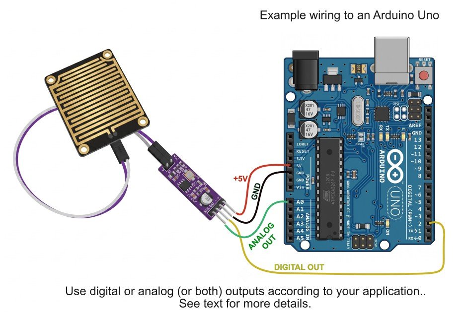
wiring example
Specifications
Specs

Technical Specifications
* Operating Voltage: 3.3 V−5 V DC
* Main Comparator IC: LM311 Voltage Comparator
* Output Signals: Analog (ANA) and Digital (DIG)
* Default Digital State: Normally HIGH (VCC​) when dry; active LOW (0 V) when wet
* Connections: 4-pin header (VCC, GND, DIG, ANA)

Additional Info
Details

Theory of Operation
1. Resistive Rain Sensing PCB
The external sensor board consists of two set sets of exposed, interleaved nickel/copper traces.
* Dry State: Air acts as an insulator between the traces, creating a very high resistance across the sensor terminals (J1 IN to GND).
* Wet State: Water droplet accumulation acts as a conductive bridge across the traces, significantly decreasing resistance proportionally to the amount of liquid bridging the gap.
2. Analog Output (ANA)
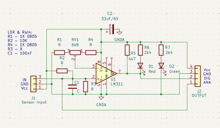
The rain board forms a voltage divider circuit with onboard resistors (R1​, R2​). As water contacts the sensor pad and decreases its resistance, the node voltage directly reflects this change. This variable voltage signal is routed straight to the ANA output pin, allowing microcontrollers to read analog values (via ADC) to estimate rainfall intensity or surface wetness levels.
3. Comparator & Digital Output (DIG)
The module utilizes an LM311 voltage comparator to generate a clean, chatter-free digital threshold output:
* A reference voltage is set at the non-inverting input (V+​) using the onboard trimpot (RV1​).
* The variable sensor voltage from the rain pad is fed into the inverting input (V−​).
* When dry, V−​ remains higher than V+​, keeping the comparator output High-Z/pulled HIGH (Normally HIGH).
* When raindrops lower the sensor resistance, V−​ drops below V+​. The LM311 pulls the output pin (DIG) LOW to ground, simultaneously turning on the red OUTPUT INDICATOR LED (D1​) to signal wet conditions.

Schematic
How To

Adjustment Procedure (Digital Sensitivity Calibration)
1. Power Up the Circuit:
* Connect VCC to 3.3V or 5V and GND to Ground.
* Confirm that the green Power Indicator LED (D2​) lights up.
2. Set the Dry Baseline:
* Ensure the sensor PCB surface is completely clean and dry.
* If the red Output Indicator LED (D1​) is ON while dry, turn the Threshold Adjust Potentiometer (RV1​) counter-clockwise until D1​ just turns OFF.
* Verify that the digital output pin (DIG) reads HIGH (VCC​).
3. Calibrate Rain Detection Sensitivity:
* Place a few drops of water (or a moist cloth) onto the interleaved copper traces of the sensor pad.
* Adjust RV1​:
* Turn Clockwise: Increases sensitivity (triggers easily with small water drops or light mist).
* Turn Counter-Clockwise: Decreases sensitivity (triggers only with larger amounts of water).
* Adjust until the red Output Indicator LED (D1​) turns ON and DIG drops to LOW at your desired wetness level.
4. Verify & Test:
* Wipe the sensor pad completely dry with a paper towel or cloth.
* Confirm that D1​ turns OFF and DIG returns to HIGH.
* Re-apply water drops to test repeatability and fine-tune RV1​ as necessary.

Prices and stock availability subject to change without prior notice. If you want this product but it indicates it is not in stock, chat us or simply add it to your cart anyway. Our staff will contact you to inform if we can/cannot provide the item in your order.