Menu
Menu
Your Cart

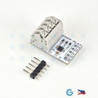
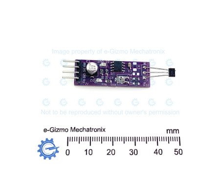
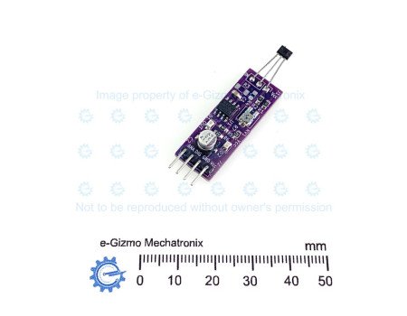
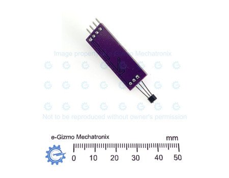
e-Gizmo Hall Magnetic Sensor Module A1314 with Digital & True Analog Output
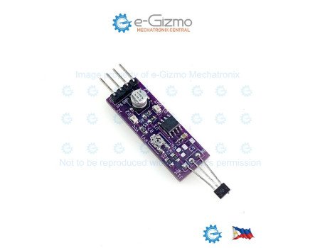
e-Gizmo Hall Magnetic Sensor Module A1314 with Digital & True Analog Output
New
e-Gizmo Hall Magnetic Sensor Module A1314 with Digital & True Analog Output
₱59.00
  • Stock: In Stock
  • Brand: e-Gizmo
  • Product Code: 211100068

High-Precision A1314 Hall Effect Sensor Module

Unlock precise magnetic field detection with this versatile A1314 Hall Effect Sensor Module. Perfect for proximity switching, speed measurement (tachometers), and positioning applications, this board provides both raw telemetry and immediate threshold switching in a compact package.

Key Features

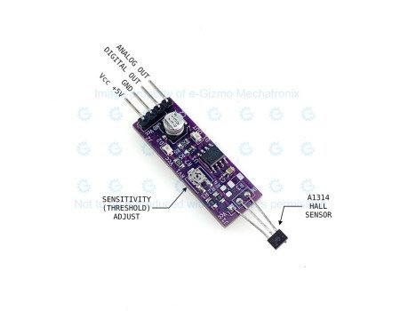
- Dual Outputs: Equipped with both an Analog Out (AO) for real-time magnetic field strength measurement and a Digital Out (DO) for threshold-triggered logic.
- Analog Output even allows the sensor to distinguish a magnet`s North or South Pole
-Onboard Threshold Adjust: Features a built-in potentiometer to easily tune the digital switching sensitivity.
- Visual Indicators: Integrated LEDs provide instant feedback for power and digital trigger status.

The Analog Advantage: A1314 vs. A3144

When shopping for magnetic sensors, details matter. Many lookalike modules on the market utilize the older A3144 sensor.

⚠️ Buyer Beware: Modules based on the A3144 cannot provide a true analog output because the A3144 chip itself is strictly a digital switch. Even if an A3144-based board features an "Analog" pin, it is typically non-functional or cloned.

Because this module uses the genuine A1314 linear Hall effect sensor, you get a true, continuous analog voltage proportional to the magnetic flux density, alongside standard digital switching.
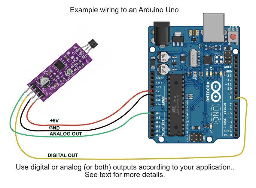
How to Adjust the Digital Threshold
The digital threshold is adjusted using the onboard single-turn potentiometer (labeled RV1). Because the analog voltage can swing either up or down from the 2.5V baseline depending on the magnet`s polarity, you need to tune the threshold based on the specific pole you plan to face toward the sensor.Here is the quick process:

Step 1: Set the Baseline
Power the module with no magnets nearby. Turn the potentiometer until the digital output status LED (D1 OUT) just shuts off.

Step 2: Tune for Your Target Polarity
Bring your target magnet near the sensor in the exact orientation you intend to use it.
- If using a South Pole (Voltage Swings Up): Turn the potentiometer in the direction that makes the LED click ON when the magnet approaches, and OFF when it is pulled away.
-If using a North Pole (Voltage Swings Down): Turn the potentiometer in the opposite direction. You are tuning the internal comparator to trigger on a falling voltage rather than a rising one.

Step 3: Test the Distance
Move the magnet closer or further away to check your trigger distance. Fine-tune the screw slightly to achieve the exact physical detection distance your project requires.

(Note: Adjusting this threshold only changes the flip-point of the Digital Out pin; the Analog Out voltage remains a continuous, unadjusted reading of the actual magnetic field.)

Specifications
General Specifications

Supply Voltage Vcc: 3.3-5VDC
Digital output: Logic level according to Vcc
Hall Element: A1314

Analog Output:

The exact analog output voltage range depends on the input supply voltage (Vcc) you provide to the module`s VCC pin. Because the A1314 is a ratiometric linear Hall effect sensor, its output characteristics scale directly with its supply voltage.

1. Quiescent Output Voltage (Zero Magnetic Field) When there is no magnetic field present (0 Gauss), the analog output (Vout) rests at exactly half of the supply voltage:
Quiescent Vout = Vcc divided by 2
At 5.0V Supply: Resets to 2.50VAt 3.3V Supply: Resets to 1.65V

2. Full-Scale Analog Output Voltage Range
As a magnet approaches the sensor, the voltage will swing up or down from that middle resting point depending on the magnetic pole (North or South).
The output architecture allows it to swing nearly rail-to-rail, typically within 0.2V to 0.4V of the supply limits under maximum magnetic saturation:
- When powered at 5V: The analog output range is approximately 0.2V to 4.8V.
--South Pole approaching: Voltage increases from 2.5V up toward roughly 4.8V.
-- North Pole approaching: Voltage decreases from 2.5V down toward roughly 0.2V.
When powered at 3.3V: The analog output range is approximately 0.2V to 3.1V.

Summary Matrix for ADC Interfacing
-Powered at 5.0V
--No Magnetic Field (0 G): roughly 2.5V
--Max South Pole Saturation: roughly 4.7V to 4.8V
--Max North Pole Saturation: roughly 0.2V to 0.3V
-Powered at 3.3V
--No Magnetic Field (0 G): roughly 1.65V
--Max South Pole Saturation: roughly 3.0V to 3.1V
--Max North Pole Saturation: roughly 0.2V to 0.3V

Note: Since the output is linear and ratiometric, ensure your microcontroller`s ADC reference voltage (Vref) matches the Vcc supplying the module. This prevents slight fluctuations in your power rail from changing your magnetic field readings.

Prices and stock availability subject to change without prior notice. If you want this product but it indicates it is not in stock, chat us or simply add it to your cart anyway. Our staff will contact you to inform if we can/cannot provide the item in your order.