Menu
Menu
Your Cart

e-Gizmo Photosensitive LDR Light Sensor Module with Analog Out
e-Gizmo Photosensitive LDR Light Sensor Module with Analog Out
New
e-Gizmo Photosensitive LDR Light Sensor Module with Analog Out
₱31.00
  • Stock: In Stock
  • Brand: e-Gizmo
  • Product Code: 211100071

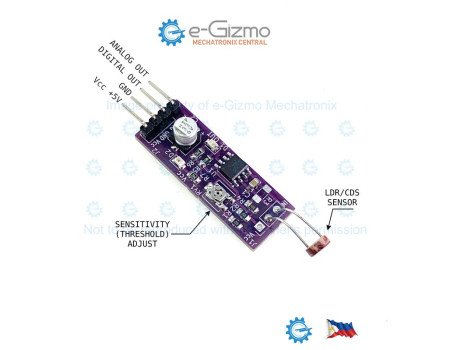
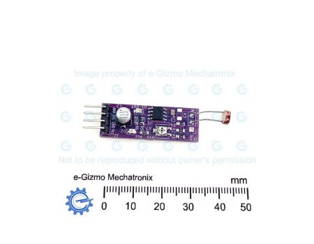
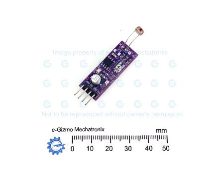
The e-Gizmo Light Sensor Module is a compact, high-precision light-sensing board designed for robotics, automated lighting control, microcontroller applications (such as Arduino, Raspberry Pi, or PIC), and industrial monitoring systems.

Equipped with a standard 5mm Light Dependent Resistor (LDR / CdS photoresistor), this module delivers both analog and digital outputs. The analog output provides a continuous voltage signal inversely proportional to ambient light intensity, while the digital output functions as a sharp threshold trigger driven by an onboard LM311 high-speed voltage comparator. An integrated multi-turn potentiometer allows fine-tuning of the trigger reference voltage across a wide dynamic range.

KEY FEATURES
- Dual Output Capability: Simultaneous Analog Output for light level measurement and Digital Output for threshold switching.
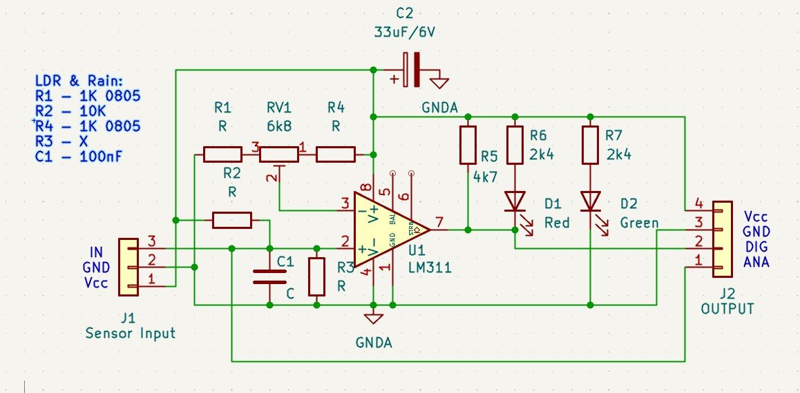
- LM311 High-Speed Comparator: Dedicated LM311 differential comparator IC (U1) with an onboard 4.7 k-ohm pull-up resistor (R5) ensures sharp, clean Active-LOW digital switching.
- Precise Sensitivity Adjustment: Trimmer potentiometer (RV1, 6.8 k-ohms) flanked by limit resistors (R1, R4) provides an adjustable switching threshold between 0.57V and 4.43V.
-Onboard Filtering: 100 nF filter capacitor (C1) on the analog sensor node suppresses high-frequency optical and electrical noise for stable switching.
- Clear Visual LED Indicators:
-- Green LED (D2): Power status indicator (illuminates when +5V DC is applied).
-- Red LED (D1): Active-LOW output indicator (illuminates when ambient light reaches or exceeds the threshold).
- Standard 4-Pin Output Header: 2.54 mm (0.1 in) pitch header for straightforward breadboard or microcontroller connection.

PIN CONFIGURATION (HEADER J2)
1. ANA (Pin 1) : Analog Output voltage signal (V_ANA) direct from LDR divider
2. DIG (Pin 2) : Active-LOW digital threshold trigger output (LM311 open-collector Pin 7)
3. GND (Pin 3) : System Ground Reference
4. VCC (Pin 4) : +5V DC Main Power Input
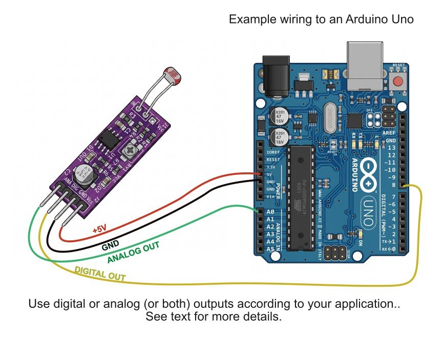
Wiring Guide


Specifications
Specs

Operating Voltage (VCC): 5.0V DC
Primary Sensing Element: 5mm CdS Photoresistor (LDR connected across J1)
Comparator IC: LM311 Differential Comparator (U1)
Voltage Divider Pull-Up Resistor (R2): 10 k-ohmsThreshold Potentiometer (RV1): 6.8 k-ohm trimmer with 1 k-ohm limit resistors (R1, R4)
Analog Output Voltage Range: VCC (Dark) down to approx. 0V (Bright Light)Digital
Output Logic: Active-LOW (Normally HIGH at VCC, pulls LOW to 0V on trigger)Output Pull-Up Resistor (R5): 4.7 k-ohms
Status LEDs: D2 Green (Power), D1 Red (Digital Trigger)
Main Header Spacing (J2): 2.54 mm (0.1 in) pitch

Additional Info
Details

THEORY OF OPERATION

1. Photoresistor (LDR) & Analog Signal Generation
The sensing element is a Cadmium Sulfide (CdS) Light Dependent Resistor connected across J1 Pin 3 (IN) and GND. It forms a voltage divider circuit with fixed resistor R2 (10 k-ohms), which is pulled up to VCC (+5V).

The resulting analog voltage V_ANA at node IN is given by:
V_ANA = VCC * (R_LDR / (R2 + R_LDR))
- Dark Environment: R_LDR is extremely high (typically greater than or equal to 1 M-ohm). Because R_LDR is much greater than R2, the voltage V_ANA remains high, close to VCC (+5V).
- Bright Environment: R_LDR drops significantly (typically 1 k-ohm - 10 k-ohms). As R_LDR decreases relative to R2 = 10 k-ohms, V_ANA falls towards ground (0V).
Filter capacitor C1 (100 nF) is connected in parallel across the LDR to ground, smoothing rapid light fluctuations and removing high-frequency electrical noise from V_ANA. This signal is exposed on J2 Pin 1 (ANA) for direct measurement by microcontroller ADCs.

2. Threshold Reference Voltage Generation
A stable comparison threshold voltage V_ref is established using a resistive divider network comprising R1 (1 k-ohm), trimmer potentiometer RV1 (6.8 k-ohms), and R4 (1 k-ohm) connected between VCC and GND:
V_ref(min) = VCC * (R4 / (R1 + RV1 + R4)) = 5V * (1 k-ohm / 8.8 k-ohms) = approx. 0.57V
V_ref(max) = VCC * ((RV1 + R4) / (R1 + RV1 + R4)) = 5V * (7.8 k-ohms / 8.8 k-ohms) = approx. 4.43V
Adjusting RV1 allows precise tuning of V_ref at Pin 3 (non-inverting input V+) of the LM311 comparator (U1).

3. Digital Switching via LM311 Comparator
The LM311 comparator (U1) continuously compares the filtered analog sensor voltage V_ANA at Pin 2 (inverting input V-) against reference voltage V_ref at Pin 3 (non-inverting input V+).
a. Dark / Below-Threshold Condition (V_ANA > V_ref):
-V- (Pin 2) is higher than V+ (Pin 3).
- The LM311 internal output transistor remains OFF (open-collector).
- Resistor R5 (4.7 k-ohms) pulls Pin 7 (DIG) HIGH to VCC (+5V).
- Red LED D1 remains OFF because there is no ground path through Pin 7.
b. Bright / Threshold Reached Condition (V_ANA <= V_ref):
- As ambient brightness increases, R_LDR drops and V_ANA falls below V_ref.
- V- (Pin 2) becomes less than or equal to V+ (Pin 3).
- The LM311 output transistor turns ON, pulling Pin 7 (DIG) LOW to 0V.
- Current flows from VCC through R6 (2.4 k-ohms) and Red LED D1 into Pin 7 to ground, illuminating D1.
- The DIGITAL OUT pin (J2 Pin 2) provides a clean Active-LOW logic output (0V).

Light Sensor Schematic


How To

APPLICATION & CALIBRATION GUIDELINES

Wiring:
- Connect VCC (J2 Pin 4) to +5V DC power supply.
- Connect GND (J2 Pin 3) to system ground.
- Connect ANA (J2 Pin 1) to an analog input (e.g., A0 on Arduino) for intensity reading.
- Connect DIG (J2 Pin 2) to a digital input or interrupt pin.

Calibration:
- Expose the LDR to the desired light level at which the output should trigger.
-Turn potentiometer RV1 until Red LED D1 just turns ON.
-When light level exceeds this calibrated threshold, DIG goes LOW (0V) and D1 illuminates.

Prices and stock availability subject to change without prior notice. If you want this product but it indicates it is not in stock, chat us or simply add it to your cart anyway. Our staff will contact you to inform if we can/cannot provide the item in your order.