Menu
Menu
Your Cart

e-Gizmo SW-18015P Vibration Sensor Module Normally High
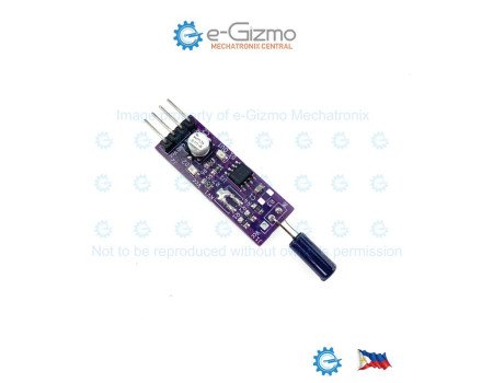
e-Gizmo SW-18015P Vibration Sensor Module Normally High
New
e-Gizmo SW-18015P Vibration Sensor Module Normally High
₱45.00
  • Stock: In Stock
  • Product Code: 211100072

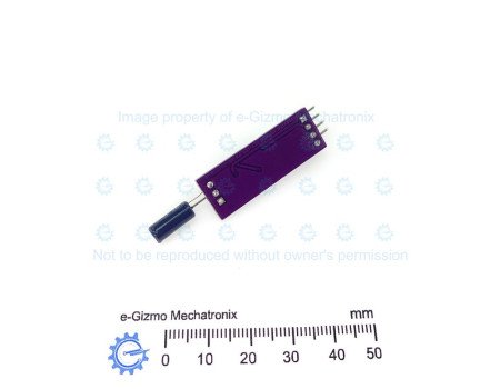
e-Gizmo Vibration Module is a sensor used to detect vibration or accelerated motion. It is based on SW-18015P, a non-direction vibration switch - it can triggered from any direction. It produces a logic low output whenever it detects motion. The module is commonly used in industrial machinery and electronic devices to monitor vibration levels. It is capable of detecting acceleration in all directions and can be sensitive to a range of vibration levels.

COMMON APPLICATIONS:
- Intrusion detection and anti-theft alarm systems
- Impact and bump detection for mobile robotics and AGVs
-Machine status and vibration monitoring
-Interactive shake-to-activate electronic gadgets

KEY FEATURES:
-SW-18015P Omnidirectional Sensor: High-sensitivity, non-directional vibration switch capable of triggering on mechanical shock or motion from any angle.
- LM311 Voltage Comparator: Integrates an onboard LM311 high-speed comparator IC for clean, chatter-free digital switching.
- Dual Signal Outputs:
-- Digital Output (DIG): Active-LOW digital trigger output for simple microcontroller interrupt pin integration.
-- Analog Output (ANA): Direct tap on the sensor input node. Since the SW-18015P is a mechanical switch, ANA and DIG can be used interchangeably in most applications.
- Stable Reference Threshold: Pre-configured fixed voltage divider (Vref = 1/2 Vcc) for consistent trigger thresholding across +5V operation.
- Visual Status LEDs:
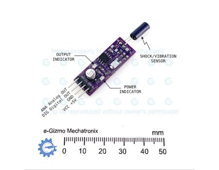
-- Power LED (D2 - Green): Illuminates continuously when the module is powered.
-- Output LED (D1 - Red): Illuminates when a shock or vibration is detected.
- Compact & Plug-and-Play: Standard 0.1-inch pitch 4-pin output header for quick breadboard and system connection.

PINOUT CONFIGURATION (J2 Connector):
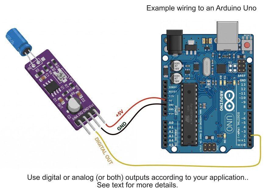
Pin 1. ANA Analog Output -Direct sensor node signal output. Functionally interchangeable with DIG in most applications.
Pin 2. DIG Digital Output - Active-LOW digital trigger output driven by LM311 open-collector (4.7 kOhm pull-up).
Pin 3. GND Power Ground - System common ground connection (0V).
Pin 4. Vcc Supply Voltage - Power supply input (+5V DC).

Note: Because the SW-18015P is essentially a mechanical on-off device, there is no appreciable operational difference between the ANA and DIG outputs.They can be used interchangeably in most microcontroller applications.


Wiring Example

Specifications
Specs

Primary Sensor: SW-18015P Omnidirectional Shock/Vibration Switch
Operating Voltage: 3.3V to 5VDC
Quiescent State (DIG / ANA):Logic HIGH via pull-up resistor
Triggered State (DIG / ANA): Logic LOW
Board Connectors: 2.54mm pitch

Additional Info
Details

THEORY OF OPERATION:

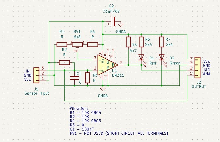
The e-Gizmo Vibration Sensor Module operates by processing the physical mechanical state of the SW-18015P switch through an RC filter network and an LM311 comparator stage:

1. Sensor Trigger & Signal Conditioning:
- The SW-18015P sensor switch is connected across the input node (IN / Pin 3 of J1). Under resting conditions, the switch contact remains open.
- Upon physical vibration or impact, the internal spring element inside the SW-18015P momentarily contacts the terminal wall, bringing the input node low.
- An RC filter composed of resistor R2 = 10 kOhm and capacitor C1 = 100 nF filters noise spikes and smooths transient voltage swings before passing the signal to the inverting input (Pin 2) of the LM311 comparator (U1).
-The raw node voltage is routed directly to the ANA pin on connector J2. Because the primary sensor is a mechanical on-off switch, the signal on ANA consists of logic-level state transitions rather than a true continuous variable voltage.

2. Voltage Comparison & Reference Threshold:
- Resistors R1 = 10 kOhm and R4 = 10 kOhm form a precision fixed voltage divider between Vcc and GND (RV1 is shorted across all terminals). This establishes a stable reference voltage at the non-inverting input (Pin 3 of LM311):

Vref = Vcc *R4 / (R1 + R4) = 1/2 Vcc (approx. 2.5V DC at +5V DC)

-Power supply stability is maintained across the comparator via decoupling capacitor C2 = 33 uF / 6V.

3. Digital Output & Indicator Logic:
-The LM311 utilizes an open-collector output stage (Pin 7) pulled up to Vcc by pull-up resistor R5 = 4.7 kOhm.
- Quiescent State (No Vibration): The input voltage remains above Vref. The LM311 output transistor remains OFF (high impedance), and R5 pulls the DIG line to a logic HIGH state (+5V). The Red LED (D1) remains OFF.
- Triggered State (Vibration Detected): When mechanical motion causes the sensor contact to close, the voltage at input Pin 2 drops below Vref. The LM311 output transistor turns ON, sinking current to Ground:
- The DIG signal transitions to a logic LOW state (0V, Active Low).
- Current flows through resistor R6 = 2.4 kOhm and the Red LED (D1), driving D1 ON to indicate motion detection.

schematic

Prices and stock availability subject to change without prior notice. If you want this product but it indicates it is not in stock, chat us or simply add it to your cart anyway. Our staff will contact you to inform if we can/cannot provide the item in your order.