


PBOT2018 and Ardublock – Line tracking sensors
03 Jul

Posted By
0 Comment(s)
2380 View(s)
Updated: 5/17/21
LINE SENSORS SECTIONS:
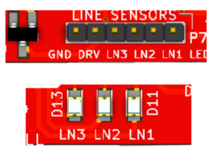
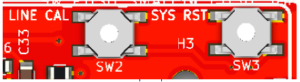
P7 - Connections for 3ch line sensors
LN3,LN2,LN1 - LED Indicators for line sensor

GND - Yellow wire, DRV - Brown wire, LN3 - Orange wire,
LN2 - Red wire, LN1 - Red wire
PROPER ULOADING:
Press and Hold the SYS RST (SW3) then switch ON the Power (SW1)
and Click Upload. Release SYS RST when done.
LINE SENSOR CALIBRATIONS:
1. After uploading your code for line sensors.
   Turn OFF the POWER switch.
2. Place the eGizmo PBOT 2018 controller to the Black line
   then Press and Hold LINE CAL and SYS RST, while pressing and
   holding the buttons, Turn ON the POWER Switch.
   LN2 (D12 LED indicator) is ON.
3. First RELEASE the SYS RST followed by LINE CAL. Make sure the
   3CH Line sensors are faces on the Black line and you will see
   the LN1 and LN3 (D11 and D13 LED indicators) are Turn ON and LN1
   is blinking. Now Press LINE CAL once for the Black color calibration.
4. Next, if the L3 (D13 LED indicator) is blinking. Place the 3CH Line
   sensors on the White track. then Press LINE CAL again once for the
   White color calibration. After that you will see all the LEDS for
   line sensors are ON. 5. Now your eGizmo PBOT 2018 Controller line
   sensors are calibrated. Then Press the RESET button.
   You can now trace the line and DONE.
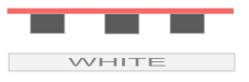
BLACK LINE AND WHITE LINE ILLUSTRATION

PBOT 2018 FUNCTION REVIEW:
- Set Line sensor for reading the black/white color.
PBOT.LS1_LEFT()
PBOT.LS2_CENTER()
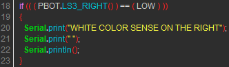
PBOT.LS3_RIGHT()
Note: Output reads: White color detected = 0 or LOW; Black color detected = 1 or HIGH;
Ex.: 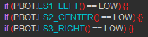
GET STARTED:
- Setting Up your Arduino IDE with ArduBlocks and the eGizmo PBOT2018 Library. (Read Here)
- In ArduBlock, using PBOT 2018,
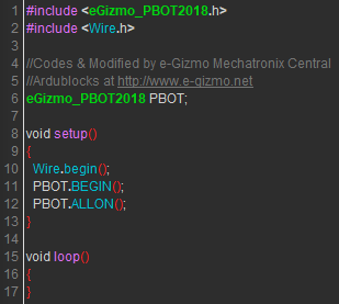
START WITH ADDING A BLOCK
“PBOT BEGIN”

Adding PBOT BEGIN Block - setting up the eGizmo_PBOT2018,wire library and Turn ON all the motors.
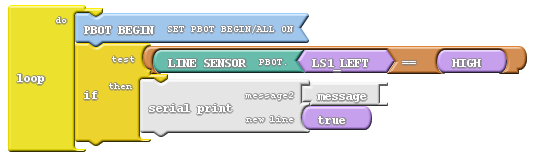
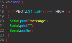
SERIAL MONITOR BY ADDING THE SERIAL PRINT BLOCK
USE THE DROP-DOWN ARROW TO SELECT SENSOR:

Click the Drop-down arrow to select immediately the line sensor
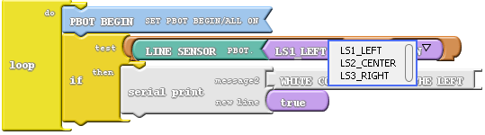
As you can see the 3 line sensors appears.
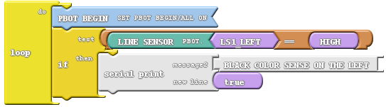
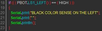
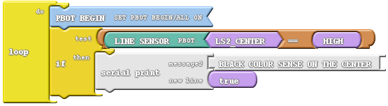
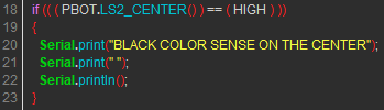
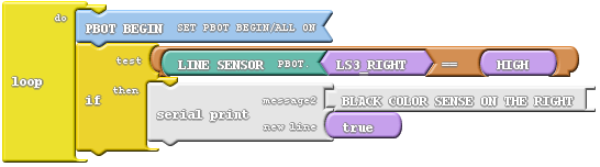
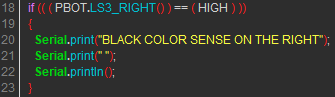
FOR BLACK LINE SENSING
//Left
//Center
//Right
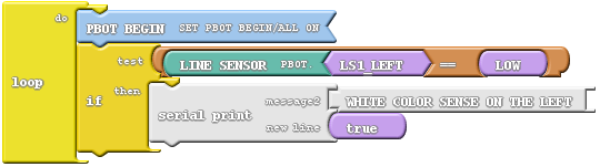
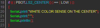
FOR WHITE LINE SENSING
//Left

//Center

//Right

- LINEBOT.ino:
 by
by 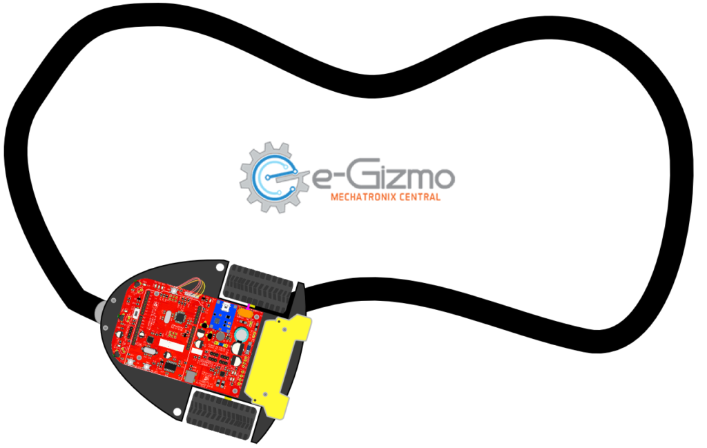
Leave a Comment